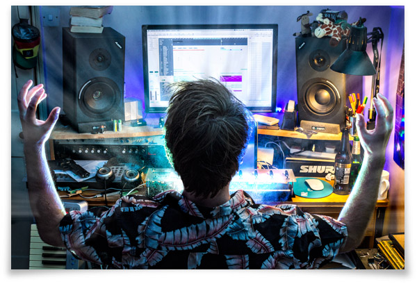
This was my creation for the project module in my final year of university. It took a lot of work to get it to a point were it was actually an enjoyable experience to make music with, rather than it being cumbersome and awkward. The core of the hardware is an Arduino Mega, which is controlled by software written in Max/MSP. The finished product and documentation actually won me the 'best final year project' award in the faculty of technology, so I was very pleased the hard work paid off.
It all came from the aftertouch control on my Edirol keyboard. It was an interesting function that could be used to add subtle modulation to a synthesizer, by varying the pressure on the key while it was depressed. The only problem was that it was quite hard to control with any degree of subtlety, which limited its use somewhat. I wanted to be able to trigger a note and then continuously modulate it, in a way that was controllable and fluent. To extend the idea further I wanted to have an interface that could be programmed to a specific set of notes or scale, so that different harmonic series could be explored while rejecting unwanted notes.
To do this I decided to remove the element of touch altogether, swapping physical keys for proximity sensors. The idea was to align a number of them in a row, representing ascending notes. Then each would be assigned a 'threshold' of proximity to begin to trigger the note associated with it. So, I set out to choose a platform to design the device on, the type of sensors that were appropriate and the best way to prototype these into a usable product.
After scouring datasheets I found the SHARP GP2D120 [Link to datasheet] to be the ideal sensor for the job. Using infra-red light, it could detect the distance to an object within its beam range of 4-30cm. This would cause the sensor to output a voltage between 0.2-3.0V, proportional to distance. Sensors with a greater range were available but they had a much higher starting height (i.e. wouldn't detect very close to the sensor, which was important for a device intended to be used at a desk). Looking at the data for the sensors response off angle I decided that a spacing of 60mm was appropriate, while also considering the width of a hand and not making the device too long. 8 sensors were chosen as 8 notes are in a regular musical scale.
I wanted LEDs to light up each channel when it was triggered, providing visual feedback. I also wanted RGB LEDs inside the device to give a light performance that interacted with your playing. I knew that the Arduino Mega had enough channels of PWM output (which I could modulate the duty cycle of to vary the brightness of LEDs) so this was one of the main reasons for choosing that prototyping platform.
A final design note was that any one person only has two hands, so the need for function buttons on each channel was a consideration. A function button could 'hold' or 'mute' a channel, or behave as an on/off switch in a step sequencer, among many other things. I had originally designed the device to have an LED above and below each sensor, but the bottom LED was replaced for a button.
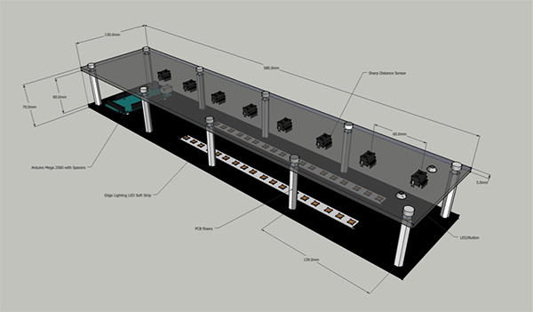
With these specification points a design was made in SketchUp, which is visible above. Two sheets of acrylic, spaced apart with tall PCB risers were used as this would make prototyping easy. The top panel is frosted acrylic so that it transmitted diffused light from the LEDs below. Each sensor would have its own associated white LED, mounted through the frosted acrylic, which varies its brightness proportionally to the sensor output value. Channel feedback LEDs were to be mounted above each sensor, and a button mounted below. The arduino is on the left, mounted on short risers and a space directly above it is left for interface buttons.
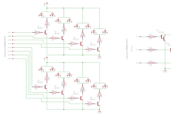
The LEDs all needed driving from the arduino PWM output pins, but as they could only provide 30mA of current a set of drive transistors were needed. A schematic was made with the intention of quickly prototyping the circuit onto stripboard, keeping the design as simple as possible. High current Darlington transistors were employed to drive the 3 channels of the RGB LED strips. The white LEDs draw approximately 45mA of current at full power, so they only needed a small transistor. These transistors would dissipate very little heat anyway as they were switching from full power to 0 at a high rate, based on the pulse width output by the arduino. Note on the schematic above there is an error, the white LEDs are placed in parallel, which can cause problems. In the end there would only be one LED per channel so the current limiting resistor was changed.
After all the components were purchased they flew together fairly quickly. It shows what a good plan and schematic does for a project, and SketchUp really helps as all of the dimensions are printed out. The acrylic sheets were ordered online pre-cut as I didn't have the facility to do it myself cleanly. I did drill the panels with a bench drill though.
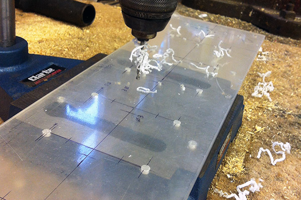
Drilling out the mounting holes. 5mm for LEDs, 3mm for the M3 mounting bolts and 4 mm for threading the wires through the panel.
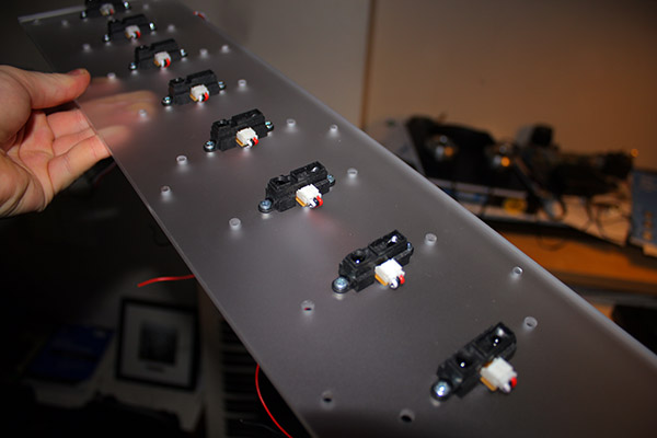
The SHARP sensors turned out to be expensive for what seemed to be a pair of infra-red LEDs and a tiny circuit. Almost £15 a piece. On top of this they were not wired, rather they had a JST style 3 pin connector (+5v, GND and Vout) which was sold separately at £2. I believe they may be a little cheaper now, but still I think the low demand for them in small quantities keeps them pricey.
The way the sensors were mounted was for ease of prototyping. If I was to make this again I would machine square holes in the acrylic and mount them from below, possibly using slightly thinner acrylic. For now that was too much effort, and how do you make a (neat) square hole in acrylic anyway?
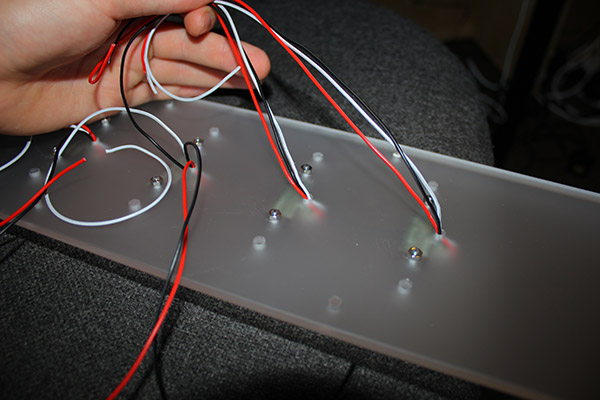
Drawing the wires through the top panel. Every sensor, LED and button was hard wired to the Arduino.
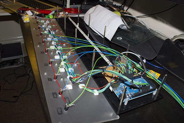
The wiring is almost finished here. The buttons are now installed (on the left row), mounted through the top panel with epoxy resin. The pull-down resistors were soldered directly to the buttons as this was the most efficient way of installing them. At this stage I was getting concerned that the sheer quantity of wires and mounting clips on the top panel would start to impede on the light show projecting from below.
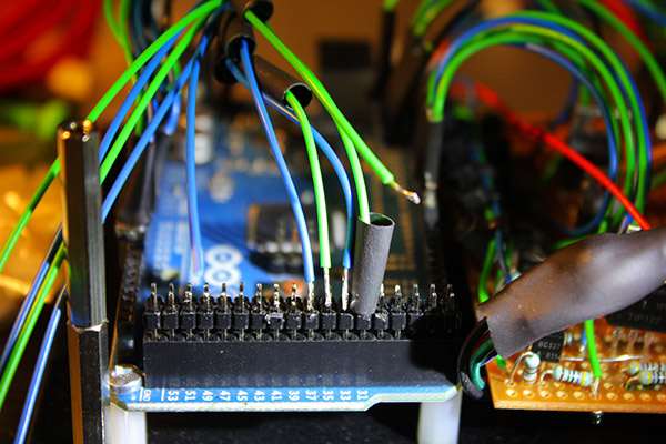
Hand wiring the top panel's wires to DIL connectors.
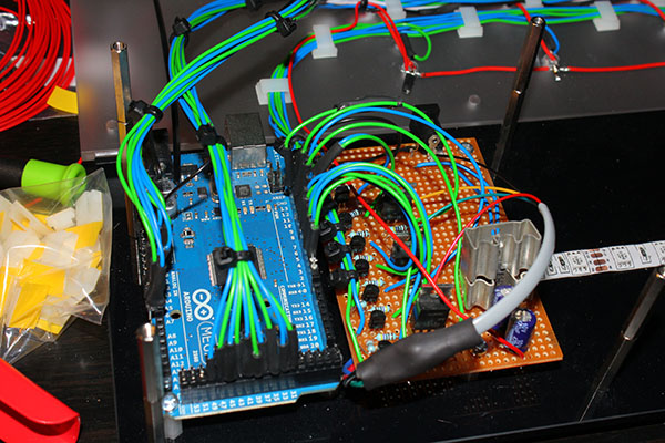
The fully wired Arduino and LED driver board.
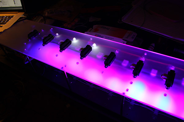
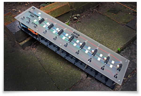
The first test illumination. This was before the buttons were glued into the top panel. You can see the white LEDs working at the top too. All of the wires didn't actually look too bad through the diffused acrylic, which was a relief.
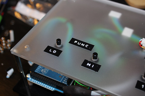
Function buttons installed and working. To label everything up I used my Dymo Junior label embosser, which is fantastic. It is a very erratic device that stamps labels letter by letter into an adhesive strip. You can't beat that retro/terrible look they give.
The Arduino had a piece of code loaded to it called the Standard Firmata from the Arduino Library. This was a communication protocol that allowed the computer to address each of the Arduino's inputs and outputs through the USB port. An open source project called Maxuino then worked alongside OSC-Route on the computer to communicate with the Arduino, based on my programs written visually in Max/MSP.
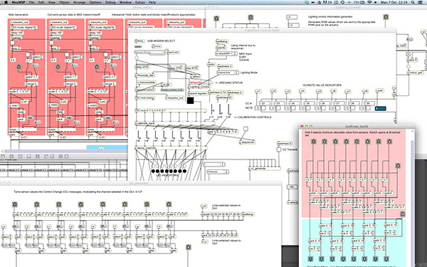
The Max/MSP patch got very large very quickly. Nearly everything needed to be written out 8 times, one for each channel. I could have used the ~Poly object but I wanted the flexibility of adjusting the individual channels with ease.
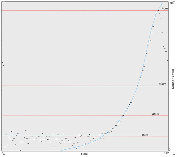
This graph is a plot of distance against software sensor level. The input range of the Arduino's analogue inputs is 0-5V, but the sensors were only outputting up to 3V. As the Arduino has a 10 bit resolution on its analogue inputs scaling in software was not going to cause any noticeable loss of accuracy. Note on this graph the steep drop off when the interrupting object gets closer than 4cm, This actually proved to create some interesting playing nuances, such as almost completely opening a channel up (as if a hand was placed around 20cm) when you placed your hand flat on the sensor. Random noise on the sensors output was also an issue and had to be filtered out. A balance between noise reduction and fast response was necessary so a section on the control panel was allocated to calibration. If you look at the above graph the noise frequently jumped above the 30cm line, so the effective range of each sensor needed to be reduced to stop random triggering.
When the programming was complete the software needed a control panel. All of the user controllable variables were selected and a layout was chosen. The idea was to make the user work from left to right like a book to fully program the device. The design was produced in Photoshop based on a few sketches I had made on paper. At the top the image of the flightdeck was taken from high up to eliminate perspective, then processed to sharpen it up. The software demonstration video is below.
Also the name was chosen, after much thought. FlightDeck was meant to inspire thoughts of flying through a field of notes, unrestricted by any 'keys'. Furthermore, the flight deck of an aircraft is somewhere that has control inherently associated, which is what I would like to believe my controller brings to the production environment.
A photograph of the finished FlightDeck. The labels are complete, and a power button is added to the top left corner.
The short, cheesy demonstration video I was asked to make as part of my university submission. Some people suggested it was akin to a M&S Food advert... In the corner is me playing the music in the background throughout the demonstration.
Demonstrating the software side of operating the FlightDeck. Excuse the audio - my audio interface has destroyed itself so this is the MacBook's microphone.
I had a brilliant time building the FlightDeck. At times I was close to pulling my hair out with the software, even though it was programmed visually, but this was a big learning experience. Next I want to learn C to program it all hard to a microcontroller. In its own right the hardware cannot do anything without the software, so I would like to change this.
The best part of this project was finishing the hardware relatively quickly, leaving me with a platform for developing a very interactive piece of kit. It was essentially an Arduino that linked the computer to an array of sensors, buttons and LEDs, all of which could be interpreted in any way the software liked. I still think the software could be developed a lot further, but for now its finished. One idea I had was implementing an 8-step sequencer that cycled over each sensor, with each one storing a different note.
The interface of an instrument affects the sound it creates as much as its method of sound production. Technically a piano and a violin are both stringed instruments, but the way the user interacts with them means that they both have their unique sound and the styles of music they compliment. This is no different for the FlightDeck, and its dynamically interactive operation makes it seems to be most at home around atmospheric and ambient music that evolves and morphs over time. It is not the instrument to play Für Elise on.
Back to projects