
Look here: http://www.theicelight.com. As a photographer I thought it sounded pretty useful. An LED torch with short-throw, high power white light. Essentially a portable window's worth of light for those shots where the light isn't right. The only problem is it costs £400 for what is basically a glorified torch. They try to sell the torch on the merit of its 'daylight balanced, flicker free light', when realistically this is not that hard to achieve. The right choice of LEDs with a constant current DC driver and you're pretty much there.
I decided that I could build my own for a lot less than what IceLight were charging, and maybe even improve the design in some respect along the way. Maybe.
The IceLight puts out 15W of daylight colour temperature light. It has lithium ion batteries for a running time of an hour ,while keeping the weight reasonable. It is dimmable and has a flicker free output for smooth video footage.
I decided that I would try and top those specs a little bit with my design. For starters, I had some 3w LEDs of the right colour temperature, so 6 of these would give me an 18W output. Also I could use a Lithium Polymer battery instead of a Lithium Ion, as LiPo cells can be manufactured long and thin (allowing a greater battery capacity in the context of a baton shaped torch enclosure).
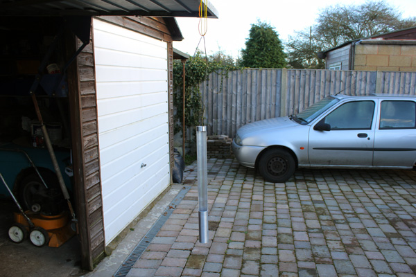
First off, I got a rough idea of the size of this torch so that I could order some aluminum. I knew that aluminum tube with a 38.1mm (1.5") inner diameter was readily available and aluminum bar with the same width was too. The idea was that I would mount all the LEDs and electronics onto this bar and slide it down inside the tube so that it lined up with the diffused lens. This aluminum bar would therefore also act as a heatsink for the LEDs and the drive circuitry. I purchased a 500mm piece of tube and bar, then started chopping.
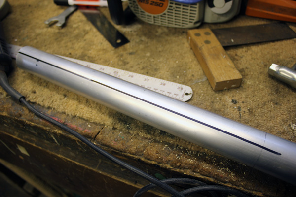
Cutting a 'window' out of a piece of aluminum tube wasn't particularly easy with the tools I had available. After marking out the cut points I decided that the best way would be to roughly cut the opening with an angle grinder, then hand file the edge down to its final dimensions.
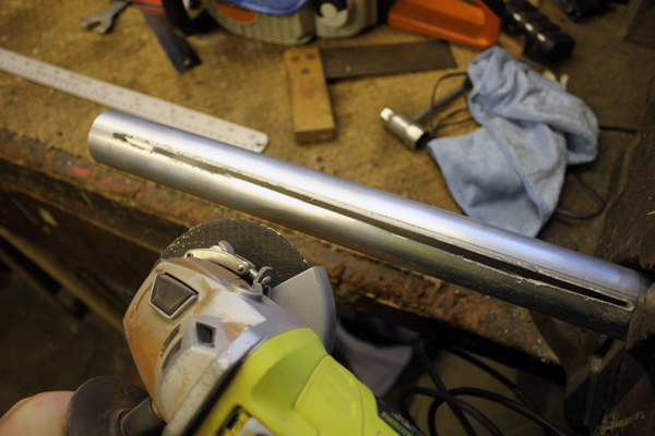
As the cut got further away from the vice the aluminum started singing so loud that it was uncomfortable to listen to even with 20dB attenuating ear plugs in.
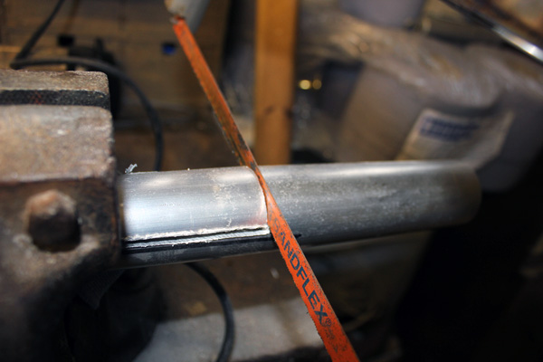
The cuts were joined using a hacksaw.
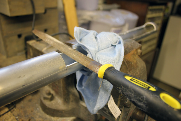
Then began the filing. This took a couple of hours overall, but was the safest was to ensure a good edge. I did get impatient and try and use the angle grinder to remove more material at once, but it was too unpredictable.
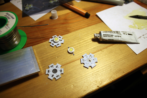
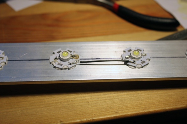
Using a dot of ThermoGlue I bonded 6x3W LEDs to heatsinks. I used the heatsinks to isolate the LEDs from the aluminum bar and add a little more thermal capacity. Also the solder pads were useful because I was going to point-to-point wire the LEDs. Once the glue set the LEDs were soldered down.
The LEDs I used were around 5500K colour temperature. This was a little bit warmer than I would have ideally liked, but these were what I had lying around. When I was testing them against daylight they had a very slight hint of magenta perceivable to the eye. However when the light of the LEDs was photographed next to daylight any difference was almost impossible to detect.
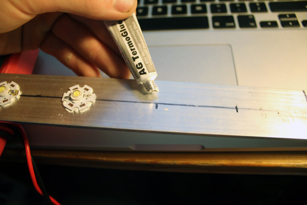
More ThermoGlue to bond the heatsinked LEDs to the alum-ilium bar.
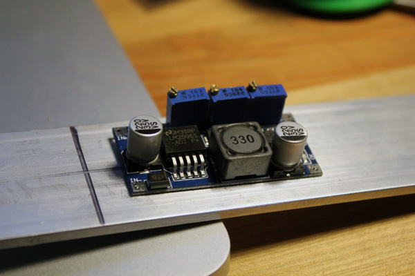
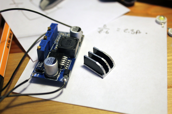
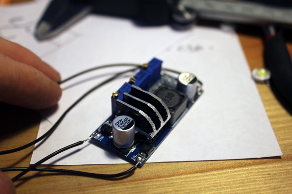
This little circuit was going to be my current driver. I brought a number of these from China over eBay for something ridiculous like £2 each including shipping. They are constant current drivers based on the LM2596 buck converter. The third trimmer potentiometer on the right hand side controls the output current, so the plan was to desolder this and add a larger potentiometer. By adding series and parallel resistors to a standard pot I could control/restrict the brightness range of the torch.
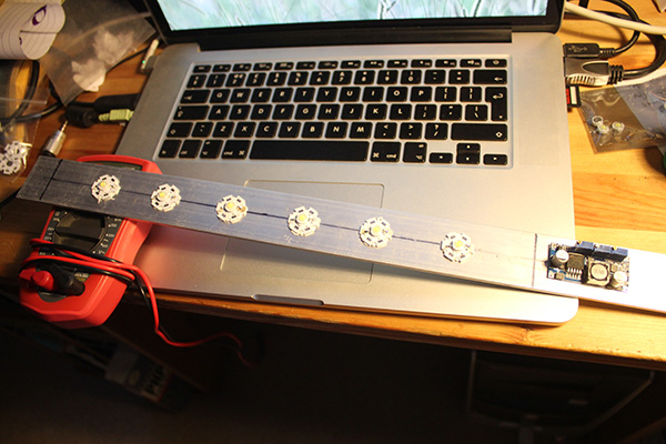
The LEDs all glued in place. Working out the best place to mount the current driver.
Beginning the point-to-point wiring.
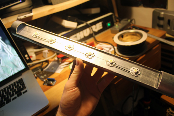
A quick test-fit inside the case.
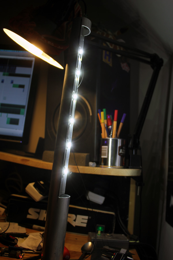
Using a bench PSU (12V) I fired up the torch for the first time. The light output was staggering! The only issue I had at this stage was heat. At full output the LM2596 chip was getting extremely hot. To combat this I was going to ThermoGlue it to the aluminum bar and add a little heatsink.
A corner was cut off a bigger heatsink and filed down so that it would fit inside the tubular body.
Then glued to the chip.
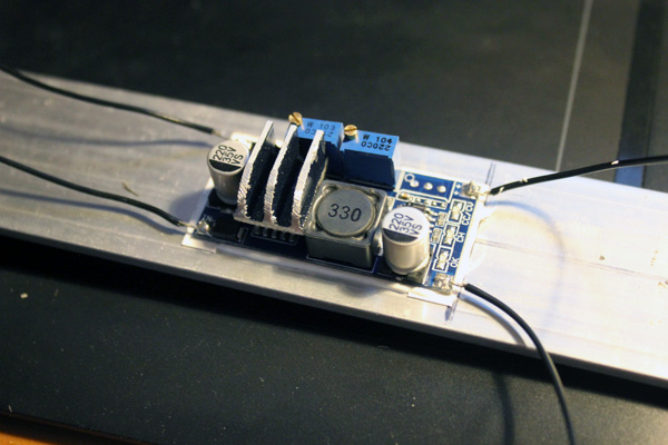
The current driver was then glued in place, using a piece of thermal rubber to isolate it electrically. Note the trimmer pot that controls current output has been removed.
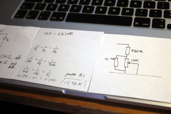
To work out what series and parallel resistor I needed on my potentiometer I made some measurements. First I set the torch to its maximum output current, then desoldered the trimmer pot and measured its resistance. Then re-soldered it and did the same for the minimum. The values required were pretty unconventional, so I brought in some precision resistors from Rapid.
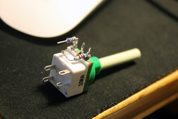
Here are the precision resistors soldered to the potentiometer. I chose a switched pot so that powering on and brightness adjustment were done from the same control. (less drilling!).
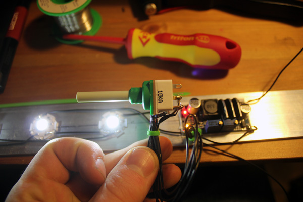
The potentiometer solderd to the PCB and correctly switching and varying brightness.
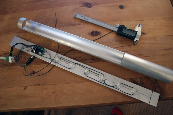
Here's where we are so far, an alumilium bar with LEDs and current driver, just waiting for a power source and an enclosure that needs drilling and painting. Getting there!
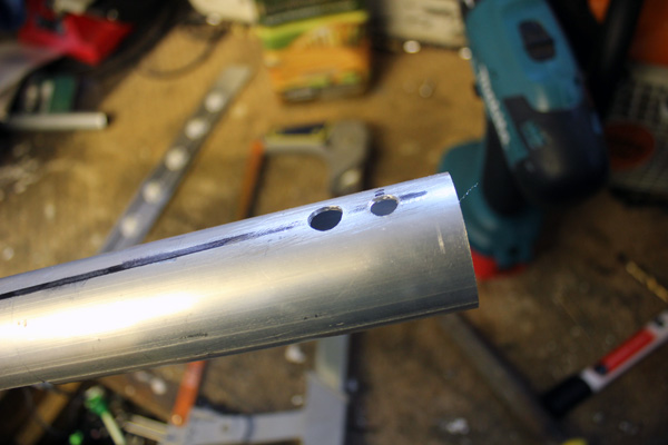
Here are the drill holes for the potentiometer and the DC (charging) input. This was the first design where I was going to use NiMh batteries and trickle charge them. After hours of searching for the right battery for me I decided that the charge density of NiMh cells was just too low- and they were typically cylindrical in shape. This meant they didn't make effective use of the cavity in the torch. After much thought I decided I would go for a 3 cell lithium polymer battery. This would give a healthy 11.1V (average) to play with. The only problem with this was that lithium batteries are very sensitive to under and overvoltage. I needed to think of way of charging them (they typically need a 'balanced' charge, where each cell is brought to exactly the same voltage individually) amd preventing the cells from damage.
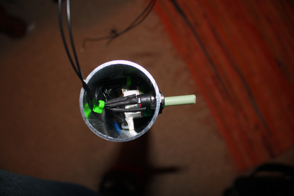
The DC jack in place. I soon realised I could not fit a balancing charger inside the torch body, so I would have to have it externally. The DC jack was to be replaced by a 4 pin mini XLR.
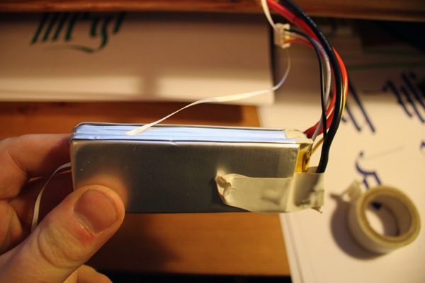
Here is my LiPo cell. 2200mAh 11.1V. Extremeley high charge density. It was quite an expensive battery, but it will hopefully be worth it. It took a lot of searching to find the biggest one I could squeeze in the torch. You can see the dental floss between two of the cells. Using floss and label remover the cells could be gently pulled apart. They are very fragile and any peircing or separation of the layers would render the cell useless.
At full brightness I was recording a current drain of 1.64A from the cell (at 11.1V). This is a power draw of 18.2W. Considering the relative efficency of LEDs and the current driver a lot of this is going to be turned into light. Also, a 3 cell LiPo's 'full' voltage is 12.6V, which is more like 20.6W draw. This is a lot of light, and hopefully over an hours worth of battery life.
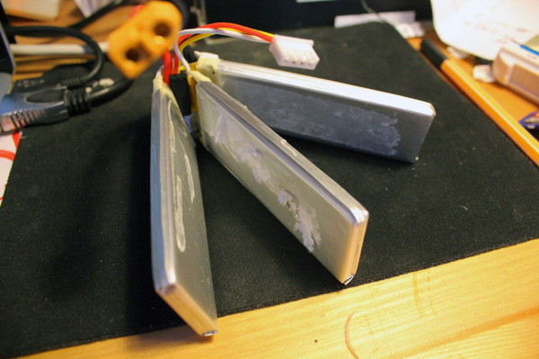
The three cells separated. I watched a video on Youtube of someone trying to do this and he eventally came to the conclusion that it was impossible. Naptha (lighter fluid) or label remover is the best way. Soak the pack then gently draw some string between the cells that is also soaked in the solvent. Final note - tape up the terminals while you do it or very big sparks can be an issue.
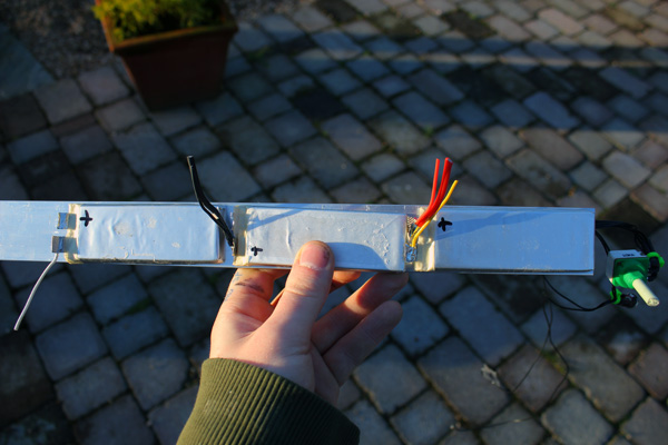
Using epoxy resin the three cells were glued to the alumilum bar.
Another shot of the glued cells.
Hanging up the body ready for painting on a primer layer.
First coat of primer.
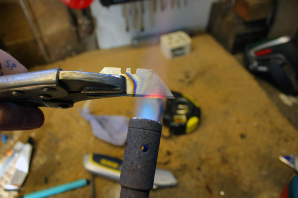
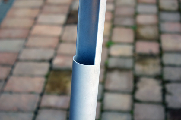
The next challege (while the primer dried) - making the lens. I had a piece of acrylic tube with an outer diameter of 1.5". It slotted perfectly inside the alumilum body, all I needed to do was half it. The method I came up with was to hold a stanley blade with mole-grips in a blowtorch flame.
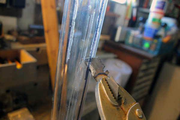
The blade kept enough heat in it to cut for about 5cm at a time, so it wasn't that difficult in the end..
The two separated pieces of acrylic.
The primed torch body with the lens fitted inside it. The lens is to be 'diffused' but here it is just transparent acrylic.
The black satin goes on.
This is another little circuit that came off the slow boat from Asia. It is a lithium battery protector. Like the other PCBs it is thermal glued to the alumilum to sink heat. It is there to stop the cells dropping below 2.75V. This is a little bit too low for a lithium polymer battery really, but it was better than nothing. The main battery protection is provided by the current driver. It needs and input-output voltage difference of over 2V to work. The 'empty' voltage of a 3 cell LiPo is 9V (3x3V), and the LEDs are asking for 7.4V (as they are in series pairs). When the battery drops to 9.4V the current driver no longer is a constant voltage source and the light output of the LEDs drops greatly. A sure indicator that its time to switch off and charge the torch. If you miss that indicator the little protection circuit kicks in.
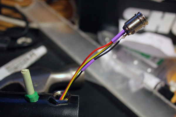
As I mentioned earlier, the DC jack had to go because the balancing charger sits outside the torch. This is a 4 pin mini XLR socket. They are really well made and provide a very good connection. It did mean that I had to file the hole out larger, and the way the socket wires in means that the electronics module can't be slid out without de-soldering the socket. I might add an inline connector to allow for this.
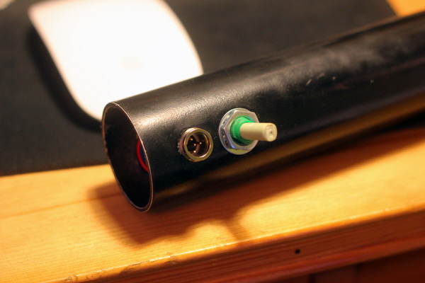
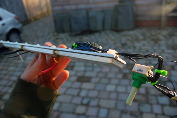
A view of the socket and potentiometer. I need to find a knob soon.
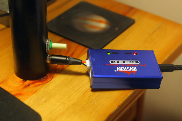
The balance charger. Works a charm! Its quite a slow charger as it pushes all the power through the balance lead, but it will do for now. The torch can operate while charging too. I will probably modify the lead so there is more cable between the charger and the torch but for now this works.
I don't know if its bothering you too, but havent the last few photos had that really nasty colour-cast from the tungsten lighting? I need some sort of portable diffused 'daylight' source...
Back to projects